Designing The Best Aluminum Castings
Once a casting design is finalized, it is difficult to obtain alterations or concessions. The time for collaboration between the design engineer, product engineer, manufacturing process engineer, and casting engineer is before the design is set. This methodology and planning at the front end of the product design and development phase can save a manufacturer and customers valuable time, cost, resources and product launch deadline targets. Web-based tools are effective in communicating complex shapes and details with the team members, who might be geographically dispersed through the globe.
There are limitations to “fixing” a problem with a product when it is in the downstream stages in a metalcasting facility (e.g., through traditional roles and responsibilities such as manufacturing process engineering, production engineering, quality assurance engineering). Unless the design engineer has considered the finished cast product from the metalcaster’s viewpoint and manufacturing requirements, the end results will not be optimal, economical or satisfactory.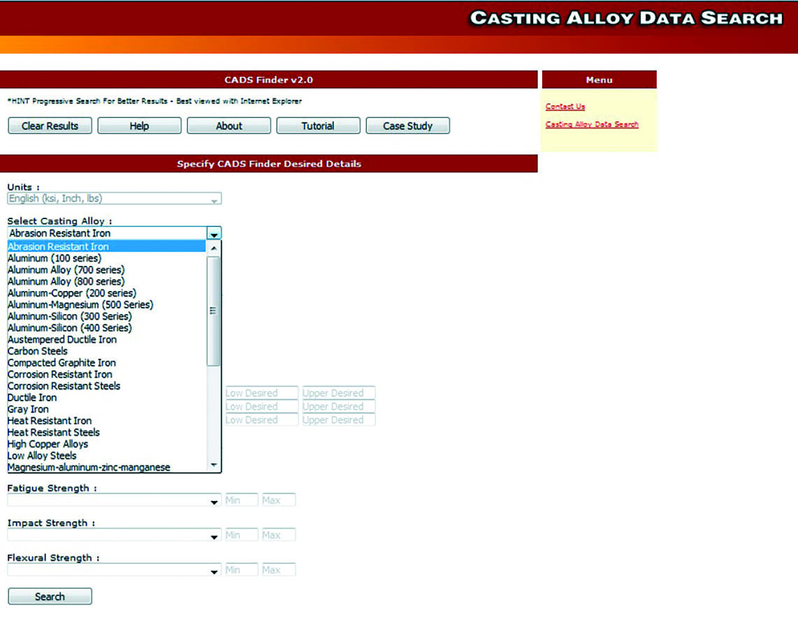
Therefore, aluminum casting designers must have a good working knowledge of the casting process and the related manufacturing processes, production processes and equipment used.
The design engineer is usually the customer and will have a list of design constraints, boundary diagrams with neighboring components, aesthetics and performance criteria to meet–within an extremely tight product launch deadline. In that same reality, the manufacturing process engineer or casting engineer is usually the casting supplier and will be able to present physical limitations or opportunities that will impact product aesthetics, performance, shape and quality.
Such issues could range from ingate placement, riser design, cooling channels, fluidity in thin sections, solidification sequence, cycle times to meet volume demands, machining, quality testing criteria, or even tooling material design. The key to success will be transforming the casting design requirements into the casting specifications, including testing requirements.
The ideal situation would be if the design engineering team and manufacturing process engineering team were allowed sufficient time to develop a carefully planned compromise over all constraints. There will likely be no solution to all issues and some attempts might even be contradictory (i.e., pour molten metal into a thick cast section followed by a machine finish vs. thin as-cast section requirement).
The objective here is not to produce the “perfect” casting (at a significant cost to the customer) by “over-designing” but to make a product that conforms to specifications. Over-designing a casting always results in higher costs. All parties should compromise in terms of:
Product
performance.
Quality acceptance criteria.
Rejection costs.
Product
appearance.
Acceptable final piece price.
When correctly designed, aluminum castings have numerous advantages over similar parts produced by many other manufacturing methods or cast in other metals.
Predesign Considerations
Before starting any casting design, a preliminary study should be made to determine the basic alloy type/system (for example, 200 series vs 300 series aluminum) and casting process that will be used in making the production runs of the part.
For example, it is not good practice to plan and design the prototype and early production parts as sand castings with the thought of later changing over to permanent mold or die castings. In many instances, the sand cast design may require considerable redesign to accommodate other casting processes.
It is also possible the alloy chosen for sand casting may not be suitable for either of the other processes. An example of a basic difference between the two processes would be the solidification rate. One of the questions that could be asked is: Given that permanent mold or diecasting would generally produce higher mechanical properties than sand casting, would this mean that the product may not require thick sections as designed for a sand cast version? Alternatively, for prototype, equivalent strength grades of alloy must be selected so that the strengths are comparable between the two processes. This simple example could be presented as cost saving and product performance opportunities to the design engineer by the manufacturing engineer—if this level of technical counsel and advice is presented at the front-end product design and development phase.
Depending upon the component’s application, various standards are available, such as ASTM International (formerly American Society for Testing and Materials) for general engineering and power industries), SAE (Society of Automotive Engineers for the automotive industry), AMS (Aerospace Materials Standard), MIL (U.S. defense standard, MIL-STD), ISO (International Organization for Standardization), DIN (German Institute for Standardization), UL/CE (European Conformity), which assist the design engineer in selecting the particular casting alloy grade as well as developing the casting specifications and requirements from a regulatory point of view.
Once the process choice has been finalized, the next consideration is to design the part to accommodate the process. If the proposed casting is large and has a complex configuration (requiring costly pattern or mold equipment) and a high casting production cost, an analysis should be done. This analysis could consider if the casting could be produced more cost effectively (i.e., as an assembly of two or more, smaller, simpler castings joined by welding or with mechanical fasteners).
Lower equipment costs, higher quality castings and lower piece costs could result if these details were investigated.
After the general form of the casting has been established, full consideration should be given to the location of the gates, risers, cooling channels and chills to ensure a sound casting. In sand, considerable flexibility is possible as far as placement in the mold. However, in a permanent mold, gates and risers are confined to the mold parting lines and in semi-permanent mold castings, chills (if necessary) usually are placed in the sand cores.
In addition to the overall casting weight, size, minimum and maximum section thickness; mechanical properties, surface finish, dimensional tolerances and near net shaped features desired drive the selection of the appropriate casting process and alloy grade for aluminum castings.
Design for Minimum Casting Stress
Aluminum alloy castings contract approximately 3/32-5/32 in./ft. during cooling to room temperature. If the design configuration is such that the mold or core effectively restricts this normal contraction during cooling, the casting might crack or develop hot tears while in the mold. At best, warping, distortion and residual casting stresses may be present.
Castings made in metal molds, hard, dry sand molds, high-pressure green sand molds, or green sand molds that contain large, dry sand cores are more susceptible to cracking in the mold than castings made in green sand alone. Green sand is less rigid and can be compressed or crushed, to some degree, by the contracting metal. 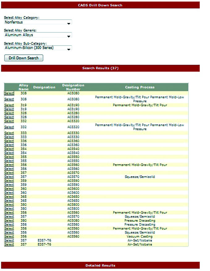
Hot tearing or cracking is also aggravated in castings where thin walls intersect thick walls or locally thick metal sections. Here, the thinner metal sections solidify, cool rapidly and contract away from the thicker metal sections, which are restrained from movement by the mold or core. There also is the possibility that portions of this thicker mass of metal may still be in the mushy stage where it has extremely low mechanical strength and is unable to resist the stresses created by the contracting members. Some alloys are more prone to hot tearing than others, so this matter should be investigated.
Tearing might even develop in straight bars that are unrestrained at the ends. As the section cools and contracts, enough resistance may develop from friction between mold and metal to rupture the casting. If the bar is uniform in cross section, no region of weakness will develop, and the bar will not tear because solidification and contraction occur uniformly across the section. However, if another member is joined to the straight bar, a hot spot is formed, and the solidification pattern is conducive to hot tearing.
Casting process simulation for filling, solidification, microstructure and residual stresses assists design engineers in validating the initial and final casting design configurations and then validates the rigging (risering and gating system) and casting process parameters such that it predicts the acceptable flaws in the critical high stress areas.
Design for Strength and Stiffness
The demand for lightweight materials with maximum performance and strength/stiffness has spread throughout the aircraft, automotive, marine and defense industries and several other commercial industries. The exacting requirements from customers and increasing competition from many other fabricating processes and materials have driven down the costs of products and components and embedded increasing efficiencies in supplier operations.
Designers must achieve strength by configuration of the part rather than by mass, and the metalcaster must control its process to produce castings that have the mechanical properties and quality necessary to meet the strength requirements of the design. Some casting processes have reached an advanced stage of development, and it is no longer difficult to achieve high quality in a well-designed casting produced in a well-equipped and properly managed metalcasting facility.
Intuitively, the design engineer may think that designing the aluminum casting wall heavier will strengthen the part; however, in aluminum castings, heavier walls have slow cooling rates, resulting in inferior mechanical properties and weight penalties. Creative design using hollow sections, which can be cored, provide higher stiffness and overall strength at much lower unit weight.
The American Foundry Society in partnership with Product Development & Analysis (PDA) LLC has developed a web-based tool to assist casting design engineers, called CADS – Casting Alloy Database Selector, which is accessible through the AFS website at www.afsinc.org. The CADS tool provides material data for design evaluations using finite element analysis (FEA), including modulus, static, monotonic as well as cyclic strain-life fatigue properties.
Figure 1 shows a list of material data and properties contained in CADS for various cast alloys including aluminum alloys, with options for exporting data, (e.g., FEA). Figure 2 shows an example of a CADS input, where a design engineer can select any of the mechanical and fatigue properties knowing the requirements (e.g. A356 aluminum). In turn, CADS finds the potential grades that can meet a design engineer’s requirements. Alternatively, if the grade is known to the design engineer, a search can be done as shown in Figures 3 and 4 for various aluminum alloys and particularly for 300 series.
Calculating Service Stresses
Many casting designers recommend using finite element stress analysis to make certain the casting will have adequate strength. However, it should be noted that mathematical stress analyses of complex designs are not too reliable, and the results should be used as a guideline that must be validated by actual functional testing for various reasons, such as non-linear and an-isotropic material behavior, size and type of the elements used, applied complex loading boundary conditions being applied with many assumptions. Stress calculations derived from this method usually will predict the performance of an uncomplicated casting in service. If a stress analysis shows the maximum operating stresses to be well within the safe limits applicable to the chosen alloy and heat treatment for a simple and well-designed casting that fails in service, the fault may lie in production process techniques or control.
Unfortunately, structural failures often are corrected by increasing the section thickness of the part, an easy practice that adds unnecessary weight and cost to the casting. Designers who use analytical techniques to develop their designs often can demonstrate that an excess amount of metal is not necessary to carry a high load (Fig. 5). Proper location and sizing of ribs and gussets usually provide the needed strength.
Experimental methods, rather than theoretical mathematical analysis, are referred for determining stresses in more complex shapes. The brittle lacquer, photo-elastic and strain gauge techniques are some of these methods.
Some shape considerations include:
Triangular shapes are more rigid than rectangular ones.
Locating beads around holes to reinforce a section is a common design practice.
Cylindrical shapes are less rigid than conical shapes.
Hollow sections as opposed to solid sections yield better properties.
Good best practice designs and collaboration at the “front-end” of the product development phase is essential for making acceptable castings in terms of piece price, quality, and delivery.
This article is an excerpt of the 3rd edition of Aluminum Casting Technology published by the American Foundry Society and available for purchase at www.afsinc.org.
Click here to see this story as it appears in the May-June issue of Metal Casting Design & Purchasing